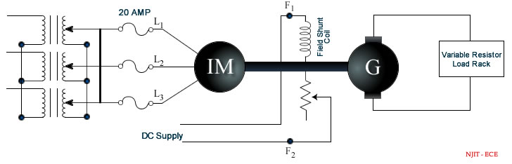
B Compute Torque Output power Input power Efficiency Input power factor and Slip for every load setting and to determine how speed efficiency power factor stator current torque and slip of an induction motor vary with load. Speed control of three phase slip ring Induction Motor 10.

Load Performance Test On 3 Phase Alternator Youtube
Current in the field windingIn.

. To conduct the load test on single phase alternator. Store this data by clicking Start Storing Data Now again increase the load by closing another load switch. I have already discussed a simple shunt regulator circuit in one of my earlier posts we can implement the same shunt regulator circuit as a dummy load for the proposed testing of alternator current through an ammeter in series with the shunt device.
Under this operating condition electrical angle between fiend axis and armature-reactio 90 Ψ 90 Ѳ 90 - Ѳ 90 Ψ 2 3 4 Which of the following will change in a 3-phase synchronous motor as a consequen variations. Regulation of an alternator by EMF MMF methods. Do not touch any live part of circuit.
3- it rotates sync around the armature. 6 No load and blocked rotor test on 3-phase induction motor. Short Circuit Test on Three Phase Alternator.
I A P W 3 PF V L-N V The power factor of resistive Jul 20 2010 The impedance at the input will be a function of the impedance values line and load and the. Load test on three phase squirrel cage Induction motor 9. 8 Load test on 1-phase induction motor.
Do not put on the supply until concerned teacher checks the circuit. A reading below 138 is indicative of a faulty alternator. Open Circuit Test on Three Phase Alternator.
The alternator rotor is connected to the variable 0-120 Vdc output of the power supply terminals 7 and N. The motor field rheostat should be kept in the minimum resistance position. 9 No load and blocked rotor test on 1.
Look at your voltmeter. 7 Separation of losses in three-phase induction motor. 17 hours agoThe phase current I in amps A is equal to the power P in watts W divided by 3 times the power factor PF times the line to neutral RMS voltage V L-N in volts V.
To Study and Measure Direct and Quadrature Axis Reactance of a 3 phase alternator by Slip Test 4. You should see a reading of approximately 138 to 144 volts. C Plot the following performance curves.
POST Lab Test 1 A cylindrical-rotor alternator on load draws a current at a leading pf angle Ѳ and with an i Ψ. Speed Control of Separately Excited DC Motor. 1- armature mmf remains constant with time.
To Study and Measure Positive Negative and Zero Sequence Impedance of a Alternator 5. The below figure shown is three phase alternator on which Direct Loading test is conductedA three phase load is connected to star connected armature with the help of TPST Triple Pole Single Throw switchBy using an external DC supply the field winding is excitedA rheostat is connected in series with the field winding to control the flux ie. The dc shunt motor winding is connected to the fixed 120 Vdc output of the power supply terminals 8 and N.
Note that the balanced resistive load is wye connected to the three-phase output of the alternator. The alternator rotor is connected to the variable 0-120 Vdc output of the power supply terminals 7 and N. Determine the full load regulation of a three phase synchronous generator by synchronous impedance method 3.
I suspect that the 2 phase load is actually expecting a single split phase voltage where the voltages are 180 from each other. Synchronization of two Three Phase Alternators by. 2-it is 90 space degrees behind the main field mmf rotor field thus it only distorts the main field.
Load test on single phase. Store this data by clicking Start Storing Data. Load Test on Three Phase Alternator - You can try with inductive and Capacitive type load.
Although an ammeter can be directly connected with the alternator output for. 5 Load test on 3-phase induction motor. Initially all switches are in open position.
As we go on inserting resistances the terminal voltage of 3 phase alternator will reduce and also the speed. If this load requires a real 2 phase voltage than the voltage phase angle will be 90. V and Inverted V curves of Synchronous Motor.
Have him rev the engine to approximately 1500 RPM. Load test on single phase transformer 5. Blocked Rotor Test on Three Phase Induction Motor.
Signal your assistant to turn off all electrical accessories and then start the vehicle. 4 V and inverted V curve of synchronous motors. Regulations on 3-phase salient pole alternator by Slip test.
All connections should be perfectly tight and no loose wire should lie on the worktable. The dc shunt motor winding is connected to the fixed 120 Vdc output of the power supply terminals 8 and N. The alternator field potential divider should be in the minimum voltage position.
Before switching ON the dc supply ensure that the starters moving arm is at its maximum resistance position. No Load Test on Three Phase Induction Motor. This is an ancient form of power distribution that may still exist.
OC SC Test on a single phase transformer 6. All three of the yellow wires when testing from yellow to yellow and so on till you have checked each combination of the three should test 02 - 05 ohms roughly and be no more than 01 difference from each of the three readings. For purely inductive load the the armatur currents are.
2 Phase Load on 3 Phase Alternator. Note that the balanced resistive load is starwye connected to the three-phase output of the alternator. V curves and inverted V curves of synchronous Motor 8.
A Perform load test on 3-phase induction motor. Stator now 2nd one is of little more consequence. Wire 1 to wire 2 reading one - wire 2 to wire 3 reading two - wire 3 to.
Plot the graph between load terminal voltage and load current. To test the machine on load we insert the resistances from resistive load bank. These facts are for purely resistive loads.
Load Test on Three Phase Alternator.

3 Phase Power Systems Have Numerous Advantages Compared To Single Phased Systems Such As Lower Conductor R Electronic Engineering Power To Weight Ratio System
Ece 494 Lab 5 Load Tests On A Three Phase Induction Motor And Measurement Of The Inrush Current

Voltage Regulation Of Alternator By Direct Loading And Solved Problem Alternator Directions Regulators
Direct Load Test On Alternator Youtube

0 Comments